Thursday, 21 October 2010

Creating the Nostrils and Lips


First the nostrils were created by using the connect edges tool to subdivide the edges around the nose into more sections so the turbo smooth modifier was act more harshly around this area of the nose. The create tool was then used to create a polygon to fill in the nostril area that was missing and finally the extrude tool was used to lift the nostrils up into the nose. The area around the nose was then altered slightly in order to give a more natural appearance.

The lower lip was created by highlighting the edges on the mouth edge of the mesh and holding Shift + Left Mouse to create extra geometry connected to the lip area. Doing this a couple of times created enough polygons to be able to manipulate the vertices into the shape of the lips. The same was then repeated for the upper lip.


Refining the Face


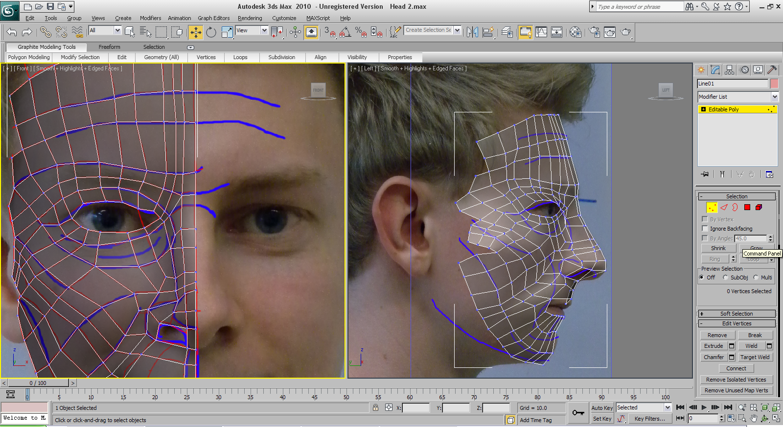
Although all the vertices were moved out from the plane I was not happy with the outcome and felt that it did not fully follow the topology of my face. Some extra lines that were missed from the topology bitmap image were added making it easier to follow the topology. After many hours of tweeking vertices the topology was sorted. A symmetry modifier was then applied to the face to mirror it on both sides and a turbo smooth modifier was also applied. The number of iterations on the turbo smooth was increased to 2 as it gave a better result.


Creating the Face


The tedious process of moving the vertices out into the position on the profile view one by one was then necessary to create the topology of the face. By toggling Alt + X the mesh could be made see through / opaque. This was very helpful as making the mesh see through meant the topology image of the profile view could be seen and so the vertices could be moved into the correct position more easily.


Drawing the Splines


Using the line tool the topology was traced and drawn on in 3Ds Max to create the mesh of the face. By turning on the snap-to-grid tool and setting it to snap to vertices it made it easier to join the vertices together so they could be easily welded later on. One spline was then converted to an editable poly and the rest of the splines were attached to it to create the polygons that make up the face. The vertices were then welded together using the weld tool.


Fixing the Topology


When starting to draw on the splines I noticed that I had a few 5-sided polygons that would ruin the topology and cause pinching of the mesh if I left them in. To fix this I had to go back into Photoshop and edit the topology lines. It ended up adding more polygons that I would have liked, but it fixed the 5-sided polygon problem. Thankfully the reference plates in max did not have to be redone as only the topology bitmapped needed to be reloaded in the material editor.


Creating the Reference plans in 3DS Max


In order to import my reference images into Max I first had to create a couple of planes to fit the materials onto. Next the reference image was imported as a material and applied to the planes. There was a problem in that the images were shown out of scale on the planes. This was fixed by applying a UVW mapping modifier and clicking the “Bitmap Fit” and flip texture buttons. Then using the Gizmo tool the image was manipulated into the correct position. The self illumination property for the material was set to on as in the view ports the material would show up black from some angles. The planes were frozen so they could not be accidentally moved when creating the face. The final problem in the stage was the fact that the bitmap showed up as a really poor resolution meaning it would be impossible to trace around the topology lines. To fix this problem a setting with the graphics driver was changed so it would match the resolution of the bitmap image. Finally the view ports were configured as recommended by Eric Maslowski to show the front view on the left and the left view on the right side as well as disabling the grid and turning on “Smooth + Highlights” option.


Drawing the Topology


With the reference images created I could now go about drawing on the topology of the face. Using Eric Maslowski’s organic modelling tutorial I started by drawing on the main lines of the face’s topology in a blue brush paying special attention to getting the cheek topology correct. Once completed a red brush was used to draw on the quads that would later be traced around in 3DS Max 2010. I started by drawing a rhombus shape to connect the main lines of the cheek topology and then moved in and completed the eye area before the rest of the face trying to make sure there were no irregular polygons with anything other than 4 sides.